Installation of Olide Door Opener on Door with Ornate Molding
Installation of a door opener on a door with ornate molding can be very challenging because there is very little flat surface against which to position the mounting plate. The brute force solution would be to cut away the molding and mount the plate against the underlying wall surface. This approach, however, would result in permanent destruction of the molding, and the problem of replacing the missing section if the door opener is removed in the future.
After much thought, a mounting solution was devised using standard wood pieces available at Home Depot. “Select pine” wood in sizes of 1 x 5, 1 x 3, and 1 x 2 were obtained. Note that the actual finished dimensions are ¾ x 4-½, ¾ x 2-½, and ¾ x 1½. All pieces are cut 21-½ inches long or as required to provide enough length to overlap the location of the vertical stud at the left-hand side of the door frame.
The pieces are assembled together as per the photos below. First the ¾ x 2-½ and ¾ x 4-½ pieces are placed with the bottom edges aligned, and screwed together using three #12 x 1½ screws. The two pieces are then placed against the molding, and the ¾ x 1½ piece is placed horizontally and positioned for a tight fit. Pilot holes are drilled through the top of the ¾ x 4-½ piece, and then screwed together using #10 x 2 screws. If carefully assembled, the completed mount will easily rest on the top ledge of the molding and stay in place with a friction fit. This facilitates accurate positioning for the mounting plate.
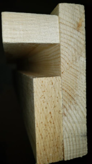
| Side View |
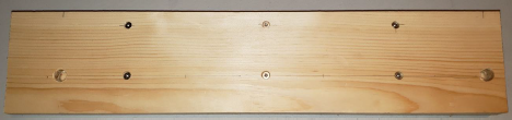
| Front View – note holes for cables at left and right |
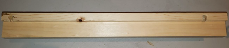
| Top View – note vertical holes for cables through the ¾ x4-½ piece. This allows wiring to be concealed. |
Next, the completed and painted assembly is placed on the ledge of the molding. The aluminum mounting plate for the opener mechanism is positioned flush with the right-hand edge, and the assembly slid to line up the left-hand edge of the mounting plate with the centre line of the hinge, as per the installation instruction manual. The wooden assembly is then secured to the vertical stud (approximately in the centre of the door frame), and the left hand stud of the door frame, using four #12 x 4 inch wood screws. Two of the screws are centred in the flat part of the molding, and two are centred in the ¾ x 1½ horizontal piece above the molding. Care is taken to ensure that the screws are tensioned so that the entire assembly is plumb and level.
The resultant assembly is very solid, and results in only two screw holes in the wood molding, and two in the drywall above the molding, all of which can be easily filled and painted over if the door opener is ever removed in the future. Because all four screws are long enough to penetrate more than an inch into the wood studs, there is no risk of the mount being unstable or detaching.
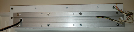
The aluminum mounting plate for the door opener is secured with four #12 x 2-½ screws at the bottom, and four countersunk ¾ inch screws (supplied by Olide) at the top. Note how the power and control wiring are concealed in the wood assembly.
The motor assembly is screwed to the mounting plate, and the position of the push arm track is determined. Note that because the motor shaft is moved further away from the door because of the thickness of the wooden mounting assembly, a 2 x 2 piece of poplar “hobby wood” (finished cross section 1½ x 1½) from Home Depot is used to compensate the offset. This piece is cut to the same length as the push arm track, and mounted to the door using four #10 x 2-½ screws.
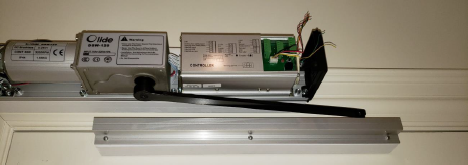
| Completed installation |
Automatic Door Control
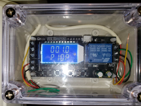
The residential elevator has a solenoid-operated door lock which is energized when the elevator arrives at a landing and the gate opens. A relay control board was purchased from Amazon and mounted in a plastic box with a transparent lid. This board obtains 27 volts DC power from the elevator control system. When the solenoid is activated to unlock the door, the activation voltage is applied to the trigger input of the relay board, which is programmed to provide a one second pulse to the Olide control system “access control” input. The relay board will not issue another pulse until the solenoid has been released and the door relocked upon closure.
The relay board has dry contacts for its output, and consequently there is no connection whatsoever between the elevator control system and the door opener control system.
Because the elevator door lock solenoid must have the door firmly closed in order to drop down and lock the door when the voltage is removed, magnetic locks controlled by the Olide opener were installed on each door to ensure proper closure.